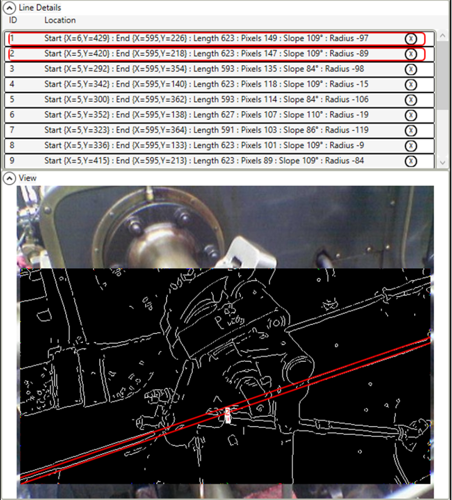
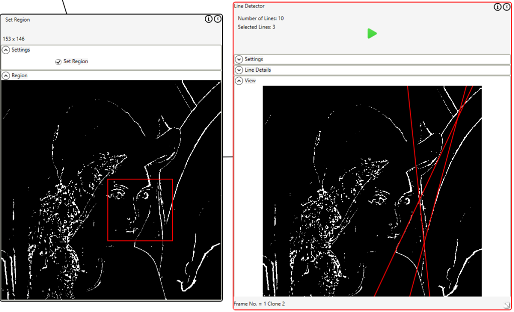
In the last blog post I showed how the line detector could be used with a Sobel filter. In this post I will show how Canny edge detection https://en.wikipedia.org/wiki/Canny_edge_detector can provide a better input to the line detector.
The latest cookbook http://sound-analysis.com/imaging-whiteboard-3-0/ shows how to use the Line Detector Control with a Sobel filter, and, how to perform Canny edge detection. This post will show how to combine both.
First, we prepare the image; repeat will help making the adjustments to the Canny edge detection, Set region will limit the entire process to a specific region. Monochrome because the Hough transform is a monochrome process.

Next, we filter the image to remove noise, and perform the initial edge detection using a full Sobel filter (includes edge direction) and gradient thresholding.

Next, we complete the Canny edge detection with double thresholding and edge hysteresis.

Finally, we use the Edge Detector to identify the most prominent lines.

In version 3.2 of the Imaging Whiteboard a Line Detector control has been added. The line detection is performed using a Hough transform https://en.wikipedia.org/wiki/Hough_transform . The lines detected are defined by the shortest distance from the origin to the line, and the angle between the x axis and the line connecting the origin to the closest point on the line. Theoretically the lines are infinitely long.
Since we want to be able to restrict the Hough transform to a specified region we want to display the detected lines in that region. Without line length restriction the display would look like:

With lines restricted to the specified region the display correctly looks like:

How is this performed? Every point on a line is defined by:

where r is the distance from the origin to the closest point on the straight line, and θ is the angle between the x axis and the line connecting the origin with that closest point.
So for each line the start and end points must be trimmed to lay on the region perimeter. Each point must be trimmed horizontally and vertically. Horizontal trimming looks like:
if (point.X < region.Left)
{
point.X = region.Left;
point.Y = _centerH – (int)((radius – Math.Cos(thetaRadians) * (region.Left – _centerW)) /
Math.Sin(thetaRadians));
}
if (point.X > region.Right)
{
point.X = region.Right;
point.Y = _centerH – (int)((radius – Math.Cos(thetaRadians) * (region.Right – _centerW)) /
Math.Sin(thetaRadians));
}
Vertical trimming is similar. The _centerW and _centerH values exist because the origin is in the center of the image, but, pixel 0,0 is in the top left corner; adjustment must be made before and after the calculation.